VE7BQH 144 MHZ
LONG
YAGI
CONSTRUCTION DETAILS
The VE7BQH 43 ELEMENT LONG
YAGI
FOR
THE LOW END OF THE 2M BAND
This 98.5' (32.349 m) long portable
antenna
was designed by VE7BQH for W0PT. This high gain (19 dbd)
antenna
is relatively lightweight, inexpensive, and very portable - it
can be
rolled
up for transport. It also has an unusually high Front/Back
ratio,
which makes it especially good for receiving weak signals when
pointed
out over a quiet direction toward the moon (such as out over the
ocean),
and facilitates an operating/equipment position very close to
the rear
of the antenna (with a very short feedline). The forward gain of
this
antenna
compares very favorably with arrays of four good 13 element
yagis;
depending
on the type of terrain over which it is mounted (near a beach
overlooking
salt water is the absolute best!), 2m EME contacts with 10-20
stations
should be possible - EVEN WITH ONLY 100 WATTS! W0PT
indicates
that
he built this antenna for
approximately $30.
This design uses .125" (3.175 mm) diameter
aluminum
elements, which are to be supported on two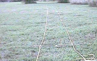 parallel non-conducting lines that will not stretch, such as
dacron,
Phyllistran
or polypropylene (will not work if the antenna is to be left out
in the
sun for an extended period of time); the lengths shown for the
antenna
elements will only be correct if .125" diameter rods are
used. If
you need to aluminum rods of a different diameter for the
elements,
please
contact me or VE7BQH so proper element lengths can be
provided.
The
antenna is meant to be suspended between two end supports, with
the two
support lines tightened to remove antenna sag. The yagi
can be
made
more horizontal by hanging a third line above the antenna and
extending
several vertical support lines (such as in the middle and
between the
middle
and ends) down from it to hold the antenna up. However,
W0PT
reports
very satisfactory operation by simply pulling the antenna tight
at the
two ends (without any further support from above).
parallel non-conducting lines that will not stretch, such as
dacron,
Phyllistran
or polypropylene (will not work if the antenna is to be left out
in the
sun for an extended period of time); the lengths shown for the
antenna
elements will only be correct if .125" diameter rods are
used. If
you need to aluminum rods of a different diameter for the
elements,
please
contact me or VE7BQH so proper element lengths can be
provided.
The
antenna is meant to be suspended between two end supports, with
the two
support lines tightened to remove antenna sag. The yagi
can be
made
more horizontal by hanging a third line above the antenna and
extending
several vertical support lines (such as in the middle and
between the
middle
and ends) down from it to hold the antenna up. However,
W0PT
reports
very satisfactory operation by simply pulling the antenna tight
at the
two ends (without any further support from above).
W0PT connected his elements to
polypropylene
support
ropes with plastic cable ties, and then the mechanical
connections was
sealed with "Plastic Rubber" to make sure the element locations
would
remain
fixed. The intended use of this antenna is to
provide
gain
in a specific direction, such as over a fixed tropo path or
toward a
particular
azimuth where the moon is intended to rise or set. It
can be
steered
somewhat (to adjust for the changing moon declination and
corresponding
change in azimuth of moonset or moonrise) by moving one end of
the yagi
(such as moving the end support point between two
trees). In an
ideal
situation, the transmission line to the Driven Element can be
kept very
short, with the yagi extending out away from the operating
position.
Be
sure to mount the rope yagi at least 12' above the
ground.
Mounting
it lower than this will cause excessive ground absorption, and
loss of
gain.
VE7BQH 43 Element Yagi Element Layout
| ELEMENT
|
OVERALL
ELEMENT
LENGTH "
|
" DISTANCE
FROM REFLECTOR
|
| Reflector |
40.6152 |
0 |
| Driven Element |
* |
12.2883 |
| Dir 1 |
38.2994 |
17.2507 |
| Dir 2 |
37.4868 |
26.4669 |
| Dir 3 |
36.7122 |
39.2276 |
| Dir 4 |
36.6674 |
55.0605 |
| Dir 5 |
36.1396 |
73.4928 |
| Dir 6 |
36.1004 |
94.2884 |
| Dir 7 |
35.8592 |
116.9742 |
| Dir 8 |
35.5766 |
141.3142 |
| Dir 9 |
35.5866 |
167.0723 |
| Dir 10 |
35.3840 |
194.0116 |
| Dir 11 |
35.2068 |
222.0145 |
| Dir 12 |
35.1176 |
250.7263 |
| Dir 13 |
35.0484 |
280.3835 |
| Dir 14 |
34.9630 |
310.6313 |
| Dir 15 |
34.8178 |
341.4701 |
| Dir 16 |
34.7270 |
372.8275 |
| Dir 17 |
34.6670 |
404.1849 |
| Dir 18 |
34.5640 |
435.8144 |
| Dir 19 |
34.5058 |
467.7981 |
| Dir 20 |
34.4646 |
500.1359 |
| Dir 21 |
34.3994 |
532.5916 |
| Dir 22 |
34.2830 |
565.4014 |
| Dir 23 |
34.2564 |
597.9433 |
| Dir 24 |
34.2092 |
630.3938 |
| Dir 25 |
34.2298 |
662.8316 |
| Dir 26 |
34.1738 |
695.3784 |
| Dir 27 |
34.0936 |
728.1672 |
| Dir 28 |
34.0068 |
760.7430 |
| Dir 29 |
33.9732 |
793.0886 |
| Dir 30 |
34.0360 |
825.2943 |
| Dir 31 |
34.0586 |
857.7106 |
| Dir 32 |
34.0776 |
890.7905 |
| Dir 33 |
34.0234 |
923.6640 |
| Dir 34 |
33.8996 |
956.4708 |
| Dir 35 |
33.9336 |
988.3597 |
| Dir 36 |
34.0288 |
1020.4431 |
| Dir 37 |
34.2656 |
1052.8131 |
| Dir 38 |
34.3224 |
1086.0181 |
| Dir 39 |
34.4460 |
1119.3873 |
| Dir 40 |
34.1236 |
1153.2526 |
| Dir 41 |
33.7610 |
1181.9335 |
*The driven element used by
W0PT
was constructed as a "T Match" as follows: Overall
length of the
1/2" (12.7 mm) diameter driven element was 37.598" (955 mm);
each of
the
two 3/8" (9.525 mm) diameter T-match sections was 15.197" (386
mm)
long;
center-to-center spacing between the driven element and
T-match rods
was
1.575" (40 mm); the driven element was fed with a standard
half-wavelength
balun 29.528" (750 mm) in length (RG-303 coax was used by
W0PT).
It may be necessary to slightly re-adjust the T-match if the
antenna is
set up in a substantially different place (or different amount
of sag,
height, etc.) than where initially tuned.
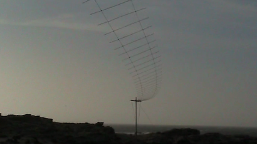
Below is a photo of the 51 element 2m rope yagi used by N7BHC in
V5
to try to make contact with ZD8BI. The wind was blowing 80
km/h,
with gusts to over 100 km/h when this
picture was taken. The wind was deflecting the middle of the
antenna about
50 cm even with more than 200 kg of tension on the antenna. N7BHC
used
3mm
Kevlar for the boom wires to minimize stretch and keep
element spacing accurate over a wide range of tensions. The Kevlar
rope
was obtained from West Marine. The yagi has a 40m boom.
UPDATE!
Lionel has redesigned the antenna to have a 50
ohm driven element. That means it can be a split dipole
fed with 50 ohm coax and you can use either ferrite toroids
around the coax to choke the RF on the shield, or use some other
method such as a Pawsey stub to match it to the balanced 50 ohm
dipole. Below is the revised design data received
from VE7BQH for this new design on January 3, 2013:
VE7BQH Rope Yagi with 3.175mm (1/8") el.
144.000 144.100 145.000 MHz
43 elements, millimeters
              3.1250    8.0000
    0.0000  1024.9750   0000.0000   0000.0000
  401.7890  0000.0000   0987.7792   0000.0000
  583.8506  0946.5488   0000.0000   0000.0000
  976.3783  0940.1720   0000.0000   0000.0000
 1381.3430  0933.6112   0000.0000   0000.0000
 1877.2152  0922.3234   0000.0000   0000.0000
 2489.4309  0917.7544   0000.0000   0000.0000
 3103.3643  0909.3950   0000.0000   0000.0000
 3735.2500  0904.0172   0000.0000   0000.0000
 4457.3101  0902.1806   0000.0000   0000.0000
 5204.1118  0899.2042   0000.0000   0000.0000
 5942.3325  0893.8304   0000.0000   0000.0000
 6695.3433  0888.8312   0000.0000   0000.0000
 7487.8125  0886.0774   0000.0000   0000.0000
 8320.8760  0885.3904   0000.0000   0000.0000
 9166.8096  0885.0514   0000.0000   0000.0000
10025.3779  0882.0188   0000.0000   0000.0000
10887.9912  0879.1972   0000.0000   0000.0000
11729.7295  0873.8140   0000.0000   0000.0000
12482.5117  0866.2224   0000.0000   0000.0000
13227.0840  0864.9466   0000.0000   0000.0000
13974.4619  0871.7912   0000.0000   0000.0000
14725.5820  0866.9242   0000.0000   0000.0000
15472.4951  0857.2578   0000.0000   0000.0000
16218.2900  0861.2754   0000.0000   0000.0000
16967.8906  0867.8694   0000.0000   0000.0000
17717.4727  0858.2322   0000.0000   0000.0000
18463.9629  0850.5968   0000.0000   0000.0000
19210.2070  0862.2996   0000.0000   0000.0000
19960.2676  0862.8776   0000.0000   0000.0000
20709.9199  0852.2834   0000.0000   0000.0000
21454.8945  0849.7156   0000.0000   0000.0000
22202.3027  0860.6222   0000.0000   0000.0000
22953.4902  0860.4088   0000.0000   0000.0000
23701.3848  0847.0908   0000.0000   0000.0000
24446.1094  0848.3580   0000.0000   0000.0000
25194.9004  0865.6212   0000.0000   0000.0000
25946.1660  0861.5302   0000.0000   0000.0000
26693.0508  0843.6596   0000.0000   0000.0000
27436.9668  0858.0192   0000.0000   0000.0000
28187.4902  0882.5146   0000.0000   0000.0000
28940.1953  0875.6558   0000.0000   0000.0000
29683.9805  0884.6826   0000.0000   0000.0000
  0000.0000   0000.0000   0000.0000
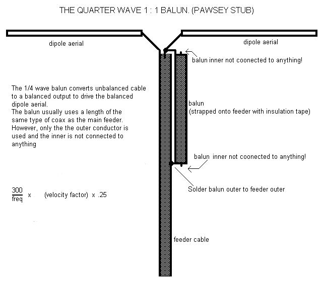
The prototype 6M8GJ I used on the E51SIX 6m EME
DXpedition also used an adaptation of a Pawsey stub, and it
worked quite well. Below is a photo of that, just to
give you some ideas. Of course, you would not need a
hairpin match with the rope yagi because it was designed for a
50 ohm split dipole from the start.


This page last revised on 3 January, 2013
