When I first received my KX3 in the summer of 2012, I ran JT65A for an hour (3w output, 10.0 VDC during transmit), and the OSC temperature peaked at 42C and finally cooled to 39C just before the next transmit period started. Since my primary interest is to use the KX3 on JT65A mode for 6m EME, good stability essential. Initially, the drift during transmit and receive periods was too extreme for reliable JT65A operation on 6m under weak signal conditions. Elecraft came up with a great temperature compensation routine which became part of the KX3 firmware, and it made the frequency very stable during full duty cycle digital mode operation on HF.
However, I still noticed a very pronounced frequency jump as things began to warm up at the start of each transmit sequence up on 6m, plus a slow steady drift during the rest of the cycle. I thought that if the OSC could be tied to a larger mass, it might be less prone to change frequency so readily. I also wanted to make sure that the KX3 could function well even in higher ambient temperatures than my very cool basement ham shack, since I have tropical DXpediton locations in mind for it.
I found what appeared to be a
manageable aluminum heat sink on EBAY that would be
large enough for me to put across the top of the KX3
(to cool the PA) and still provide enough material
for a heat sink on the bottom case of the KX3 for
the OSC. The particular piece that I chose was
offered by seller "goldpart" and described as
"100x220x18mm Aluminum Heat Sink for Electronics
Computer Electric equipment H168", weighing 472
grams. It cost $19.63 and was quickly shipped
from China.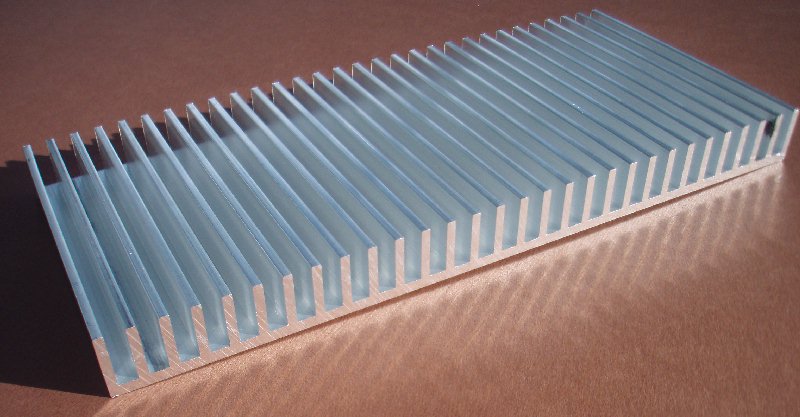 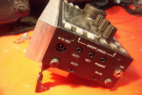 |
.
 Locations for the screws were chosen so they would avoid interfering with any components inside the KX3. The two existing holes in the rear and four in the top were used, with additional screws added (4 more in the top and 3 in the rear). AJ7LL was kind enough to donate his time and milling machine to remove sections of heat sink fins so I could fit the screws and washers into the mounting holes. The installed heat sinks are shown. Note that the heat sink on the rear still permits the KX3 to be supported by the feet. The heat sink on top of the KX3 is for the final transistors, and the heat sink on the rear is to stabilize the temperature of the oscillator. 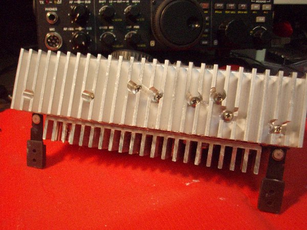 |
|
The location of the OSC on
the RF board was kindly provided by Elecraft
engineering. In order to couple the OSC to
the rear case and heat sink, product called "Gap
Pad®" from Bergquist Company was
used. Gap Pad® is a thermally
conductive while electrically insulating material
that is pliable and somewhat compressible,
depending on which particular product is
used. For this project, I chose their Gap
Pad® 5000S35 material, which had
the highest thermal conductivity. The pads
come in small sheets with a paper backing on one
side and a clear backing on the other. Both
sides are somewhat tacky, and are meant to adhere
to a case or circuit board. However, the
side with the clear film backing is somewhat
stickier.
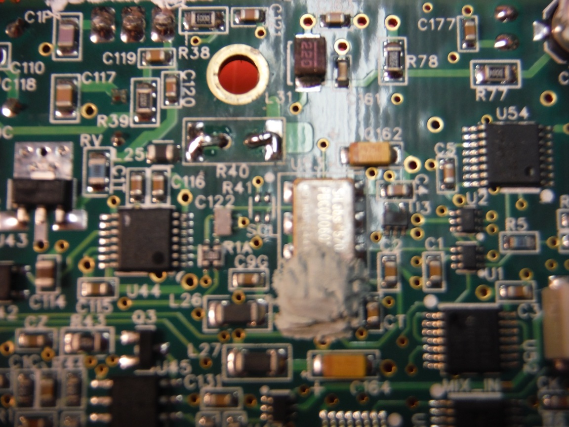
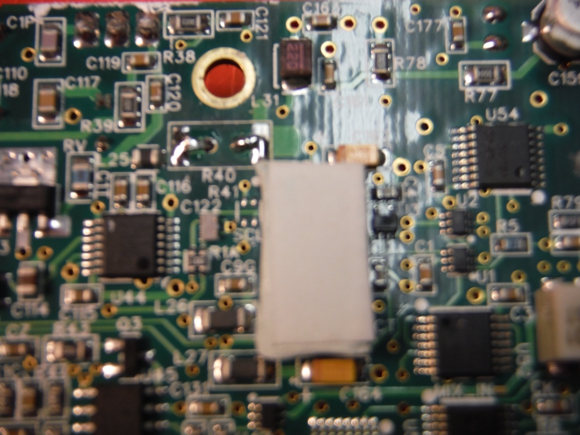
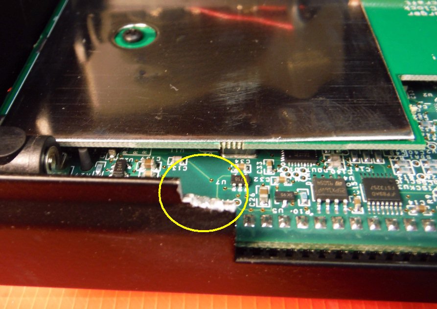
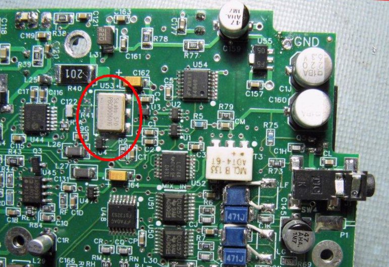 The KX3 oscillator is the silver
colored device inside the red circle in the photo
above. Also inside the red circle, but just
to the lower left of the oscillator is U4, the
temperature sensor for the oscillator.
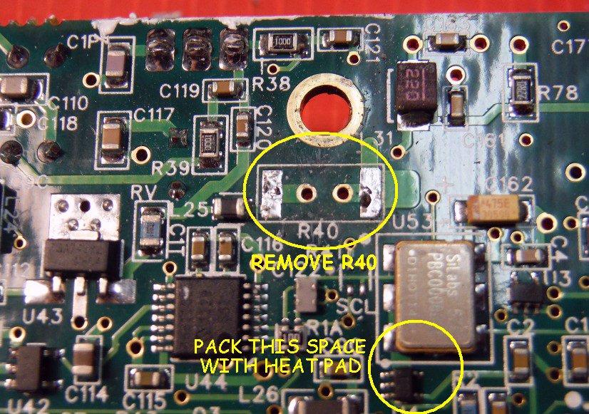
Immediately to the upper left of the circled oscillator in the above photo, you can see the 200 ohm 1 watt resistor R40 (with the large "201" marked on it). This is connected in parallel with identical value resistor R96 on the opposite side of the PC board. The instability problem is caused by current passing through those two resistors during transmit, and rapidly heating them up. Their proximity to the oscillator causes its temperature to change, creating rapid frequency drift at the beginning of each transmit cycle. It was hoped that by better coupling the oscillator to the heat sink, the rapid temperature excursions caused by those two resistors could be minimized. |
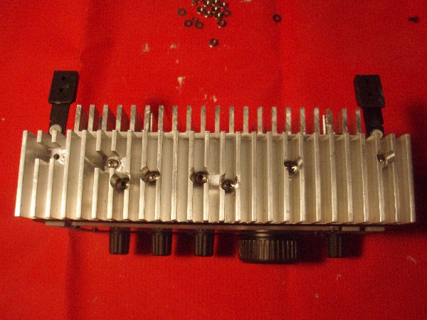
The photo below shows the rear
cover with the heat sinks installed. You can
see where located the additional screws. In
order to couple the heat sink to the PA
transistors, heat sink compound was applied to the
case before re-installing the RF
board.
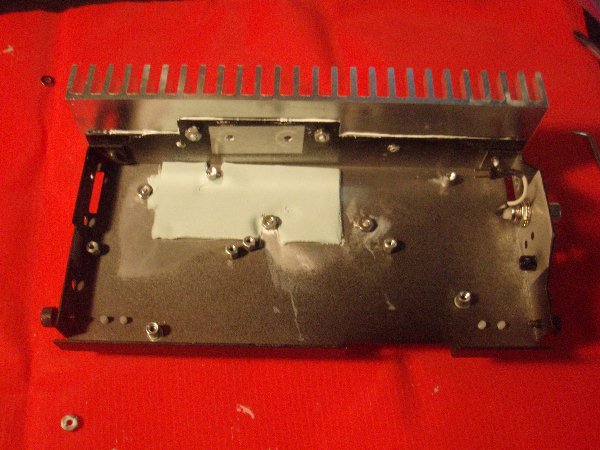 As you can see from the photo
above, piece of .100" thick Gap Pad® was
installed on the inside of the case after
thoroughly cleaning it with steel wool and
degreaser. The stickiest side was placed against
the case. A 1.5"x.875" piece of .100" thick
Gap Pad® was placed as shown over the OSC, but
positioned so it did not cover any components that
were higher off the RF board than the OSC.
When the RF board was re-installed, the gap pads
were the proper thickness to connect and bridge
the thermal gap between the OSC and the case, with
easy compression of the Gap Pad® materials.
 |
The temperature calibration routine
was done again on the KX3 with the heat sinks
installed. Then it was set up as shown
in the photo below, transmitting JT65A into a dummy
load. During transmit sequences, the KX3
display showed 10.0 VDC at 1.7A. After two
hours of JT65A operation (in my 10C basement ham
shack) at the KX3's three watt output setting, the
OSC temperature was peaking at 35C after a few
seconds, and rapidly cooling down to 33C (within 5
seconds after ending the transmit sequence).
The PA temperature peaked at 41C and also cooled
down to 33C. Note that the maximum
temperatures were much lower than those experienced
without the heat sinks, and the coolest temperature
was very quickly reached as soon as the transmitting
sequence ended. In order to successfully
use the KX3 Temperature Compensation routine, I
needed to add heat to the KX3 to get the OSC up to
an "ambient" temperature of 35 C for the initial
calibration.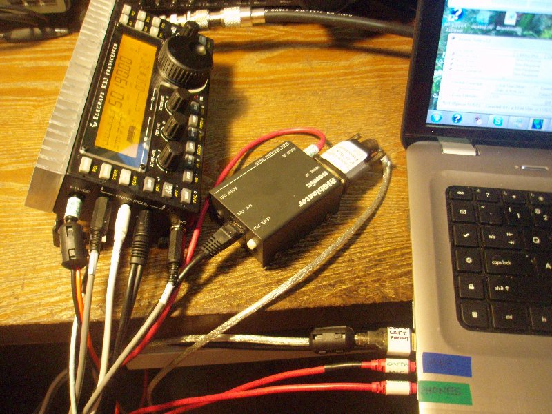 |
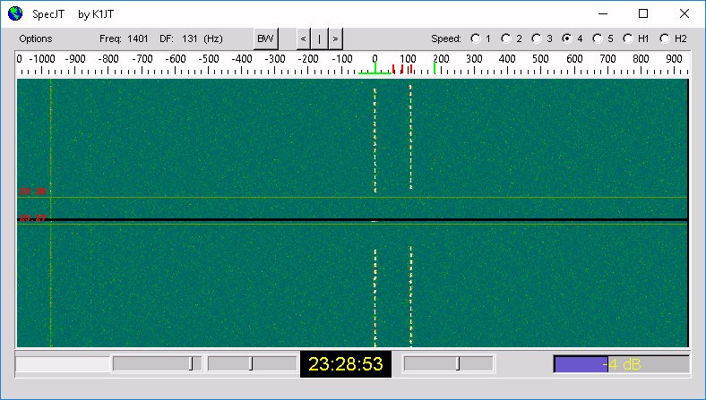
The trace of the transmitted
signal (JT65A sending "73") still seemed to
have a slight "hook" of a few hertz a
during the first few seconds of each JT65A
transmitting sequence as the OSC temperature
quickly ramps up to 35C. I suspect there
may be a way to correct for this hook when the
temperature suddenly increases, by re-running
the temperature compensation routine again
more slowly and carefully. However, I
did not go any further initially, since the
KX3 appeared to be functioning well enough on
6m, at least with strong signals.
Note that the settings shown on the WSJT SpecJT waterfall below are not typical normal operating conditions, but were set to help attenuate the KX3's tranmit signal, in order to be able to see the most detail. 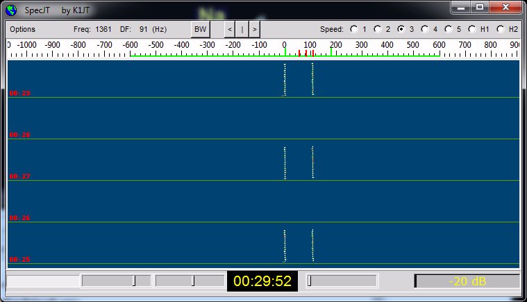 When I initially added these heat sinks in 2012, I had not verified the currently configured KX3 performance through actual on-the-air weak signal 6m EME tests, but expected that it will also be able to receive the JT65A signals without drifting since the OSC so quickly returns to its resting cool temperature, before the other station's transmit sequence begins. There was, however,a quick jump in frequency at the beginning of each transmit sequence, as you can see by looking at the bottom end of each left hand trace. |
| As you can see from the above
waterfall photo, there still was an instability
during the initial transmit period of each JT65A
sequence. In fact, during my 2015 6m EME
DXpedition to V6M, a number of stations reported
excessive drifting and difficulty copying my
signals, despite the fact that I seemed to receive
them quite well with the KX3. I suspect there
were additional other factors involved that combined
to make decoding difficult, and perhaps the KX3
heated up above the highest temperature in the
temperature compensation . However,
there is no doubt that there still was frequency
instability during transmit, when current flows
through R96 and R40, heating up the area next to the
oscillator. Itis my understanding that
Elecraft has since changed their main RF boards to
avoid this problem, but since I still had one of the
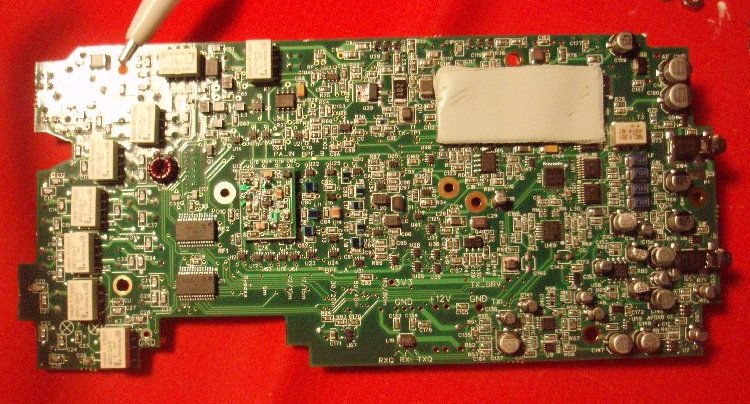
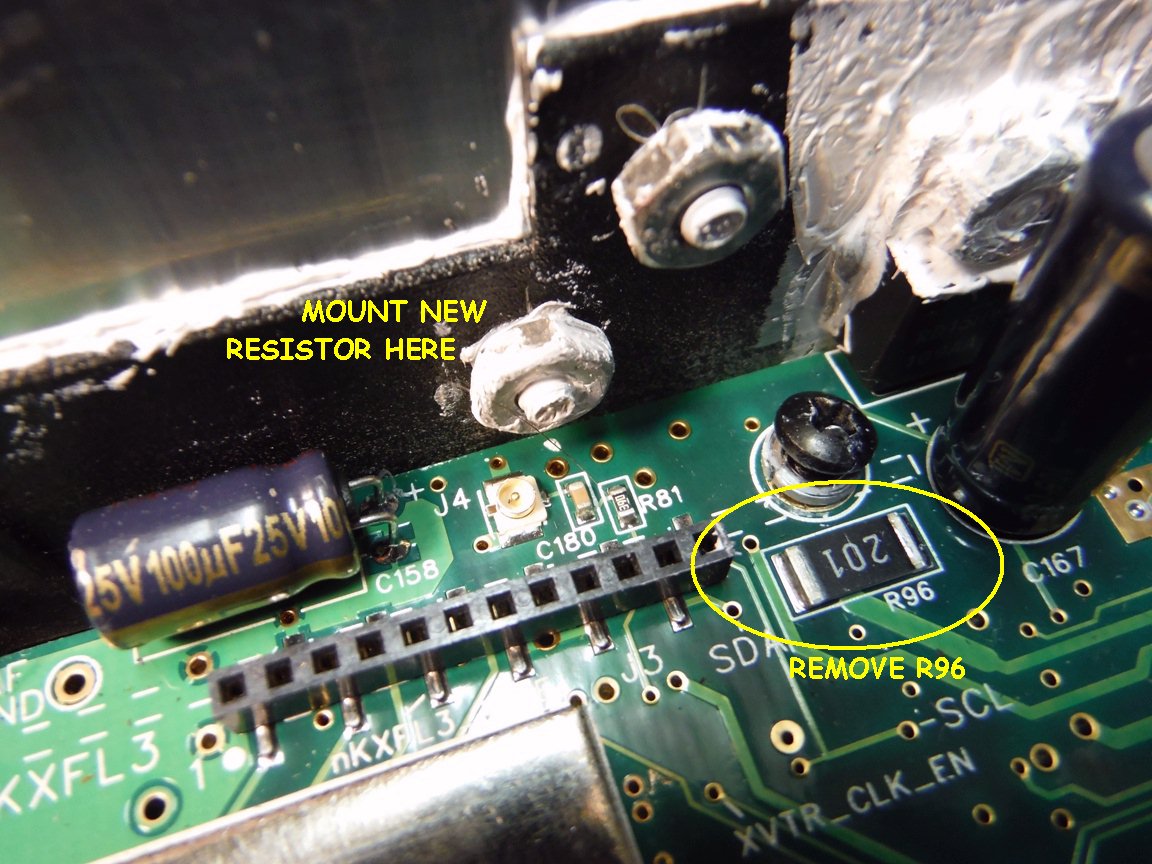
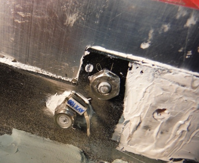
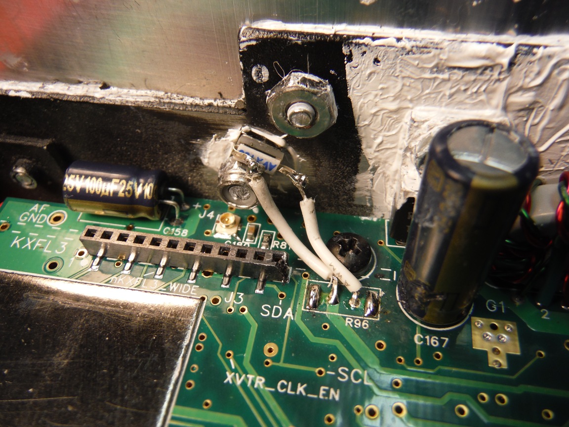
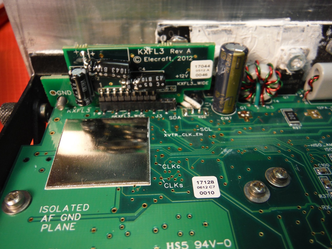
first KX3's, I had to fix the problem myself. With the even narrower bandwidth and shorter operating periods of FT8, I think it will be even more important to improve stability. The major problem with the instability on 6m was the location of R96 and R40. With the encouragement and guidance from AJ7LL and PA4K, I removed the offending R40 and R96 resistors (each 200 ohm, 1 watt mounted in parallel on opposite sides of the RF board) and replaced them with an AVX brand flange mount 100 ohm 20w planar resistor (AVX Part #RP60300R0100JNBK) that was directly coupled to the case/final amplifier heat sink. I found that a 3mm stainless steel metric size screw and nylock nut fit the flange quite neatly, and in my case a 10mm screw was the perfect size to mount the resistor through the case and heat sink on top of the KX3. As you can see from the photos, a pair of short wires were soldered to the through-plated holes where each of the resistors had been. In my case, I happened to have a mounting screw from my top heatsink nearby, and I just stuck the 3mm screw in the old 4-40 hole. Because I had to rotate the resistor up to avoid touching components on the filter board when it is installed, I also had to nibble out a corner of the front cover so it would properly close without binding on the resistor. Rather than using a second large .1" thick piece of heat pad mounted over the PC board as I had done before, I decided it would be better to more tightly couple the oscillator to its temperature sensor, U4, and limit its coupling to other components. As shown in the photos below, I tightly packed heat pad material between U4 and the oscillator, as well as all around U4, taking care not to touch any of the other circuit components. This packing also brought the height of the heat pad over U4 up to the same level as the oscillator, so another small .1" pad could be placed over top of both devices, coupling them closely. When the RF circuit board was mounted back into the bottom case, this new small heat pad joined with the larger .1" thick heat pad to couple both the oscillator and its temperature sensor to the rear panel heat sink. I did not plan to use internal batteries with my KX3, so I was not going to re-install the battery holders. In order to make sure that the board was held tightly in place and provided good pressure between the oscillator and the heat sink through the tightly compressed heat pad, separate 2-56 screws, washers and lock washers were used to secure the board where the battery holder screws had been used before. These are shown in the final photo below in which the filter board is also installed in front of the new AVX 20w resistor. |
 |
. |
 |
 |
 |
. . . |
 |
 |
 |
| After resistor replacement, heat pad
modification and re-assembly, the Elecraft
Temperature Compensation routine was done
again on my KX3. The initial frequency
reference calibration was done with the KX3 at a
temperature of 25C. The frequency
correction compensation values were collected and
stored so the KX3 frequency will be stable between
12C and 36C. The oscillator temperature now
closely follows the gradual changes in PA
temperature, since both large heat sinks are joined
via the rear panel cover. Because of the
large heat sinks, it is not anticipated that the
oscillator temperature will ever exceed 36C. For testing, the KX3 was set up transmitting the two tone "shorthand" 73 message in JT65A mode at 5w into a dummy load. JT65A was again chosen for the testing since its 48 second transmit periods would create the most sustained heating and show any frequency instability due to temperature fluctuations. Reception of the 50.200 MHz test transmissions by my K3 is shown at right. The traces are certainly stable enough for FT8 mode on 6m, and a number of contacts have been made using FT8 with my KX3. However, more detailed comparisons were done here, comparing the stability of JT65A on 6m between the K3, FT857 and KX3: http://www.bigskyspaces.com/w7gj/JT65A%20Rig%20Stability%20Comparisons.pdf Based on the above charts, it appears that there is still a wobbling from one frequency "bin" to another on JT65A mode with the KX3 on 6m. So, although it is stable enough for FT8 mode on 6m, the reliability on JT65A mode is in questionable. Of course, the KX3 is now stable enough for all modes on the HF bands. |
 |
It is not known whether the stock KX3 with only the Temperature Compensation firmware and the resistor modifications alone would provide similar performance. However, the addition of heat sinks in combination with these modifications certainly solved the stability problem, and also seems to permit higher power to be run without overheating. There now are a number of commercial heat sinks available in the event the user still needs any additional stability that is not provided through the resistor change alone. I also understand that Elecraft has introduced a revised RF printed circuit board design in the newer KX3's to address the heating issue with R40 and R96, so if you don't have the original board pictured above, these resistor modifications may not apply to your KX3.